 Why pinhole camera images are out of focus. |
MAKING THE PINHOLEThe primary influence on the technical quality of a photograph taken using a pinhole camera is obviously the hole. In order to achieve the sharpest photograph, the hole must be of the optimum size, perfectly round and should be made from the thinnest material. However, the truth is that the quality and size of the hole are not such critical parameters as one might think at first glance. Interesting pictures can be taken using almost any hole. Also, sharpness alone does not always have to be the most important requirement. Photographs from a pinhole camera are always a little less sharp and sometimes a certain amount of blur can, in itself, be an attractive means of expression. Optimal pinhole diameter The principle of the pinhole camera ensures that the image of a point is, in fact, a small disc. The smaller the hole, the smaller the disc and hence the sharper the image. However, this is only true up to a point. If the hole is too small, then light is diffracted and the image becomes less sharp. Hence, an optimum hole diameter exists for each focal length (distance from the hole to the light-sensitive material) which will create the sharpest picture. Most probably, the first person to try to find a formula for calculating the optimum hole diameter was the famous mathematician and physicist Josef Petzval in the mid-19th century. It was later improved by the British Nobel Prize-Winner Lord Rayleigh. The equation, on which he worked for ten years and which is valid to this day, was published in his book Nature in 1891. Several more formulas have appeared since that time, often derived from the same base. The formula proposed by Lord Rayleigh, revised so that the result gives the diameter, not the radius, can be written as follows:
d – pinhole diameter f – focal length l – wavelength (usually the wavelength for yellow/green light 0.00055 mm is used) To make the calculation of the optimum hole diameter or the optimum focal length easier, you can use the PinholeDesigner program. |
|||
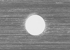 Microphotograph of a 0.2 mm pinhole. |
Making the pinhole Several companies sell precise holes of various diameters, normally made in high-grade materials using lasers (see links). However, anyone can make a good hole by themselves. A piece of metal cut from a drinks can, approximately 4 x 4 cm, is sufficient. First, using coarse sandpaper, remove the paint from the area where the hole should be, and try to make the metal as thin as possible. Then finish the surface by using fine sandpaper. Place the plate on a flat wooden block and, using a sharp needle, make the smallest hole possible. Be careful not to injure your hand and use a hard block to press down on the needle. Remove the embossed material from the reverse side of the plate using fine sandpaper. Place the needle into the hole again and, by gently pressing and turning the needle between your fingers, make the hole round. Smooth the hole again using sandpaper. It is necessary to repeat the process until the required diameter is achieved. A regular round hole in a very thin plate can be made with a bit of patience. Measuring the pinhole There are several ways to measure a hole like this. The simplest is to use a magnifying glass and ruler. However, a more accurate method is to use an enlarger. Place the hole plate and a transparent ruler in the film holder and project the image onto white paper. The greater the enlargement, the greater the accuracy of the measurement. A simple calculation will give you the scale of enlargement and, from that, the size of the hole. The following example illustrates this method: The projected image length of 6 cm of the actual ruler is 60 cm. 60/6 = 10, therefore the image is 10 times greater. The size of the projected hole image is 3 mm, 3/10 = 0.3, hence the actual diameter of the hole is 0.3 millimetres. f number In order to set exposure times, you have to know the f number of the pinhole camera. This is calculated simply by dividing the focal length by the diameter of the hole. However, it is important to bear in mind that, during longer exposures, the time must be extended due to reciprocity failure (see Determining exposure times for pinhole cameras). |
© David Balihar, 2001–